Open DIY Projects › Stuhlkreis › talking english… › EagleEi Runcam 2 gimbal
- Dieses Thema hat 15 Antworten sowie 2 Teilnehmer und wurde zuletzt vor 9 Jahren, 5 Monaten von
gyrex aktualisiert.
-
AutorBeiträge
-
21. November 2016 um 10:07 Uhr #3507
gyrex
TeilnehmerHi Benny!
I’ve finished gluing the plywood parts and now I’m looking at wiring it all up. Do you have a wiring diagram? There’s a wire spool which came with the rctimer 360 degree motor.
Also, there’s a PCB on the base in this photo, what’s this?
Is there a wiring and connection diagram for the motors and the storm controller?
Thanks for your help mate! 🙂
21. November 2016 um 12:51 Uhr #3508TeilnehmerOK, I figured out the PCB at the bottom is the storm sensor? And I found some good wiring information here: https://open-diy-projects.com/topic/verkabelung-fuer-das-eagleei-360-gimbal/
It doesn’t appear that it’s possible to wire a power lead to the camera through the wiring slipring? There’s 12 wires in total: 6 wires for 2x motors, 4 for the sensor and that only leaves 2 wires. This is really unfortunately and inconvenient – have you figured out any solution to allow routing a power lead to the camera?
21. November 2016 um 12:57 Uhr #3509TeilnehmerRegarding the slip-ring issue, could you solder a common GND to both motors freeing up a wire for a 12V feed to the USB port for the camera?
21. November 2016 um 21:17 Uhr #3514 EagleEiAdministrator
Hi John,
wiring diagram we dont have actual but my feeling tells me, this could be a good practice for John to create it!? 😉Just in few words….
the slipring has 12 wires in I use it like that:
1= MOT1 Pitch
2= MOT1 Pitch
3= MOT1 Pitch
4= MOT2 Roll
5= MOT2 Roll
6= MOT2 Roll
7= SDA (RX in case for NT IMU and I recommend to take only NT-IMU!)
8= SCL (TX in case for NT IMU and I recommend to take only NT-IMU!)
9= VCC (5V from IMU port)
10= GND
11= VIDEO OUT of Runcam
12= GND out for RuncamI dont need the Powering for Runcam! But maybe you can use the GND twie and take the 12th for 5V Power seperate!
* NT IMU!!! — in short words, never without! Why? No more I2C Errors, no more ferrits and no more 7V level, but over all, NT-IMU Logging, the best tool to vind vibrations on the Copter and Gimbal!
Actaul it is very Easy, you don´t have to solder it by your self (like my first NT CC3D IMU few month ago!) meanwhile you can order it incl. the Storm32 or as sand alone NT IMU http://www.ensys.lt/product/storm32-nt-imu-module-v2-0/= https://open-diy-projects.com/topic/nt-imu/
= https://open-diy-projects.com/topic/i2c-error/Here: http://www.olliw.eu/storm32bgc-wiki/What_is_STorM32_NT_about%3F
http://www.olliw.eu/storm32bgc-wiki/Where_to_get_NT_Modules22. November 2016 um 9:13 Uhr #3517TeilnehmerThanks for your response Benny! 🙂 I think I’ll share a GND between the 2 motors so I can run a 5V supply to the camera.
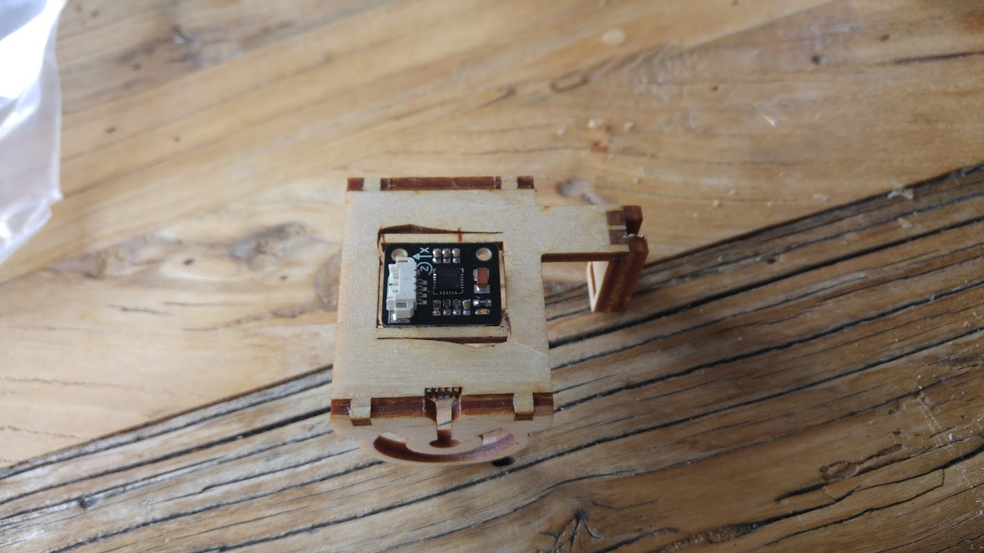
I got a separate IMU with my Storm32 board and I’ve installed it into the camera base.
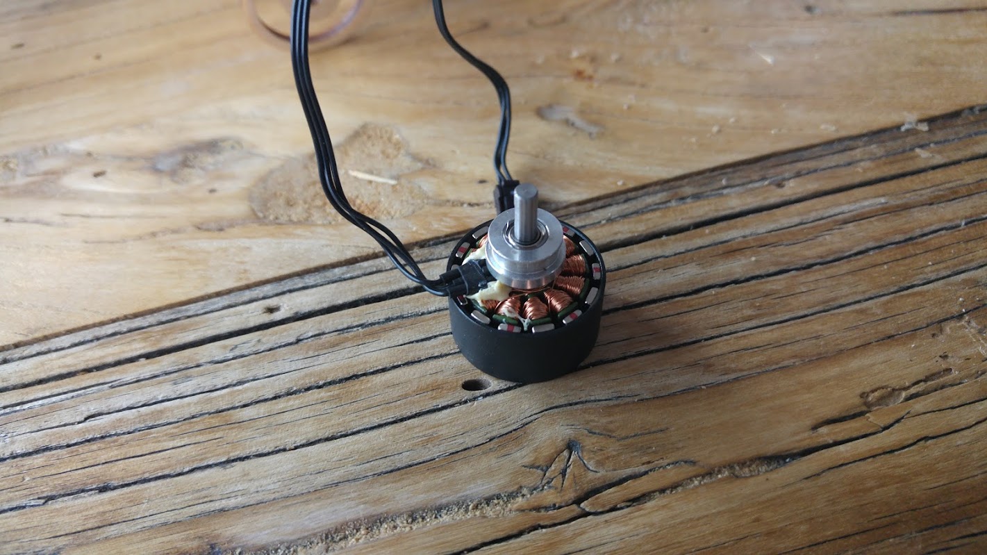
I’m sorry about all these questions but it’s hard to find a step by step guide and I’m a hobby newbie 🙂 I have a question about the walkera motors. The spindle sticks out and doesn’t allow a flush fit on the horizontal section and it sticks out on the side.
Do I need to cut this motor spindle down so it fits?
Thanks for your help Benny.
23. November 2016 um 13:54 Uhr #3524EagleEiAdministrator30. November 2016 um 13:34 Uhr #3543TeilnehmerHi Benny,
I’ve been busy building my new quad but now I’m back to building the gimbal 🙂
I’ve got a few questions…
I followed the build instructions from this video https://www.youtube.com/watch?v=0oEWqlcZsoU. My question is relating specifically to this section:

I’ve oriented my build of this section exactly as it appears here with 1. the indent facing to the right 2. The larger opening facing the inside on the left and 3. the smaller opening facing the inside on the right.
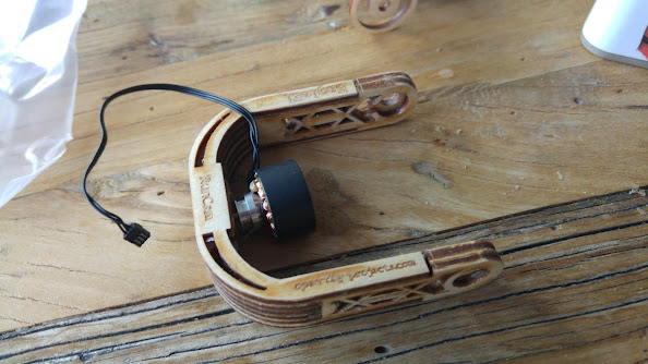
Is this correct? My motor obviously won’t fit in the small opening on the right. I’ve taken a few photos of my build and was wondering if you could take a look and tell me if there’s a problem with how I’ve built my support.
Also, I’m worried about gluing the motor in. Can you offer some advice? I’m specifically worried about gluing the motor in and accidentally gluing the bearing you can see in the second photo below. I was planning on using 5 minute epoxy glue to glue these in, is this what you recommend?
30. November 2016 um 13:57 Uhr #3544TeilnehmerOK, based on the photos from this post, my arms look completely different: https://open-diy-projects.com/topic/runcam2-aufbauanleitung/#post-2832
I think I’ll have to order a new kit 🙁 Unless you can advise how I can debond PVA wood glue?
30. November 2016 um 14:50 Uhr #3545TeilnehmerBenny, I’ve taken some measurements – can you confirm if these parts have been glued together incorrectly?
High res pic here: https://goo.gl/EtEouE
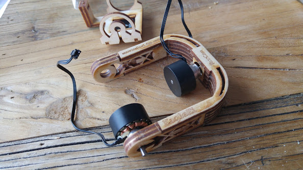
23. Dezember 2016 um 15:14 Uhr #3927TeilnehmerThanks Benny for the replacement kit since I stuffed up my first one 🙁 I thought I’d share some detailed photos for other uses on how the gimbal should look. Pay close attention to the alignment of the holes on either side of the roll arm. Hopefully these detailed photos will help others ensure that they’re assembling all the pieces together properly.
24. Dezember 2016 um 12:58 Uhr #3930TeilnehmerHi Benny,
I’ve built the gimbal properly this time and epoxied the motors in but could you please explain or show photos of how the bearing and axle assembly works? I don’t want to make any more mistakes and I’m not 100% sure how it’s supposed to fit together…
Thanks mate and merry xmas!! 🙂
John
28. Dezember 2016 um 13:58 Uhr #3937EagleEiAdministratorHi John,
today I´m back from ChristmasFamilyTime, now we can do nice things again! 😉
Your buildung looks great till now, so the next steps are the bearing and the motors.Here some pictures for the bearing and the axis:
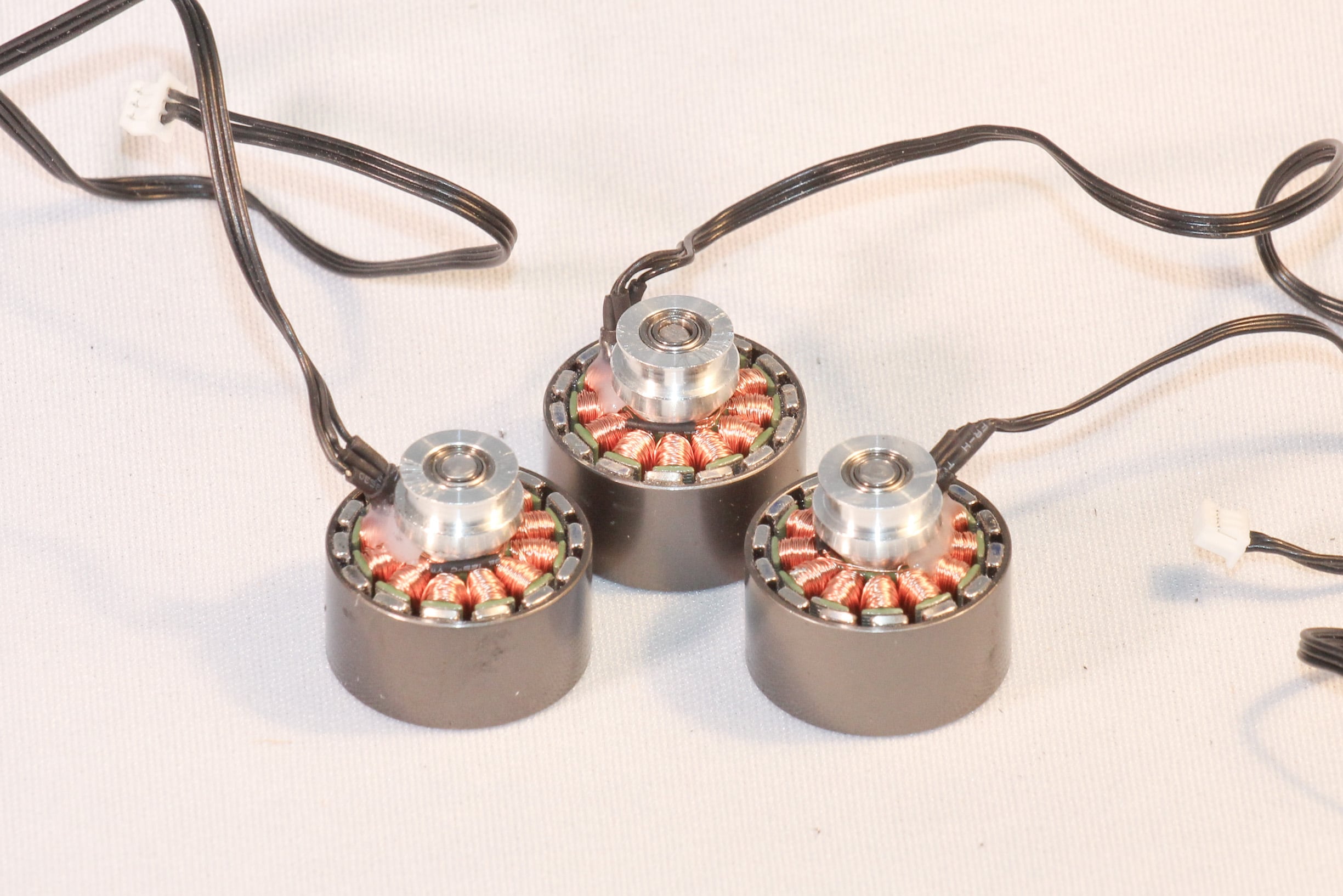
all about the motors:
https://open-diy-projects.com/wp-content/uploads/2015/03/unbenannt-1-von-41.jpg
the glueing and wireing for the Runcam is same like the other 360 Gimbals:Maybe for some german text you can use some dicct too?
English texts are always wellcome, maybe you can write some words while building too?I´m sure you will build an great Gimbal!
Best regards
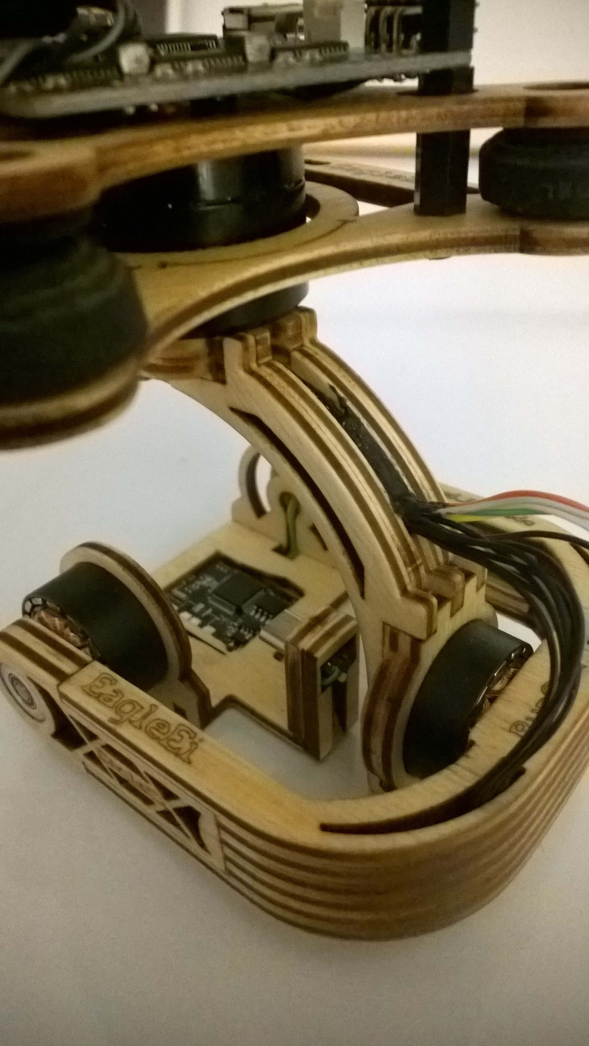
Benny4. März 2017 um 6:21 Uhr #4219TeilnehmerHi Benny! I’ve finally built and mounted the gimbal so I thought I’d send some photos. I’m having an issue with the controller resetting every 2-3 minutes so I’m asking in the rcgroups forum for help on this. Thank you so much for your help with everything and I hope my images and messages in this thread help other people looking to build this gimbal 🙂
Here’s some photos of the finished product…
4. März 2017 um 7:15 Uhr #4220TeilnehmerThe other thing I was going to comment on is that the gimbal needs to be balanced – especially the roll axis. Have you noticed this Benny? How would you advise balancing this? With lead weights?
4. März 2017 um 15:03 Uhr #4222TeilnehmerBenny, have you noticed the rctimer motors getting extremely hot? Have I wired them up incorrectly?
-
AutorBeiträge


- Du musst angemeldet sein, um auf dieses Thema antworten zu können.