Open DIY Projects › Stuhlkreis › Solar Motor „littleSunEngine“ › „littleSunEngine“ – assembly instructions –
- Dieses Thema hat 0 Antworten sowie 1 Teilnehmer und wurde zuletzt vor 7 Jahren, 9 Monaten von
luckybenni aktualisiert.
-
AutorBeiträge
-
16. Oktober 2018 um 22:18 Uhr #5035
luckybenni
ModeratorThe assembly
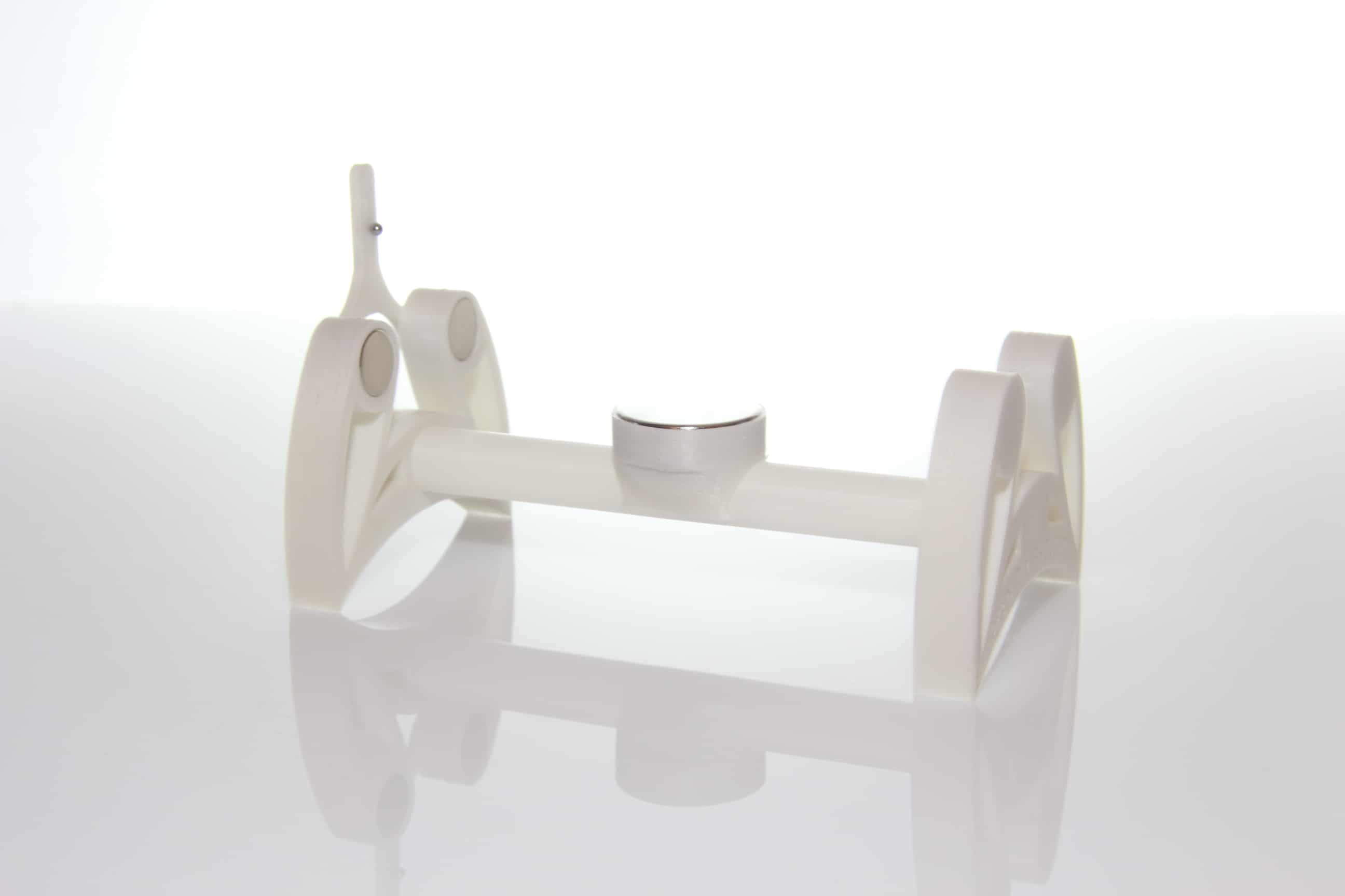
The frame assembly is possible without tools and without adhesive through simple plug connections. Make sure that the magnets in the side panels are aligned correctly. For this you can use a compass or other magnet with N / S mark. The magnets in the side panels must be aligned with the SOUTH towards the center of the frame. If the alignment fits so far, you can press the magnets into the side panels by applying even pressure by hand. Now connect the two side panels to the 3D printed tube and snap the large magnet holder into the center of the frame. Be careful with the pipe, depending on the pressure settings this can break if too strong forces are applied.
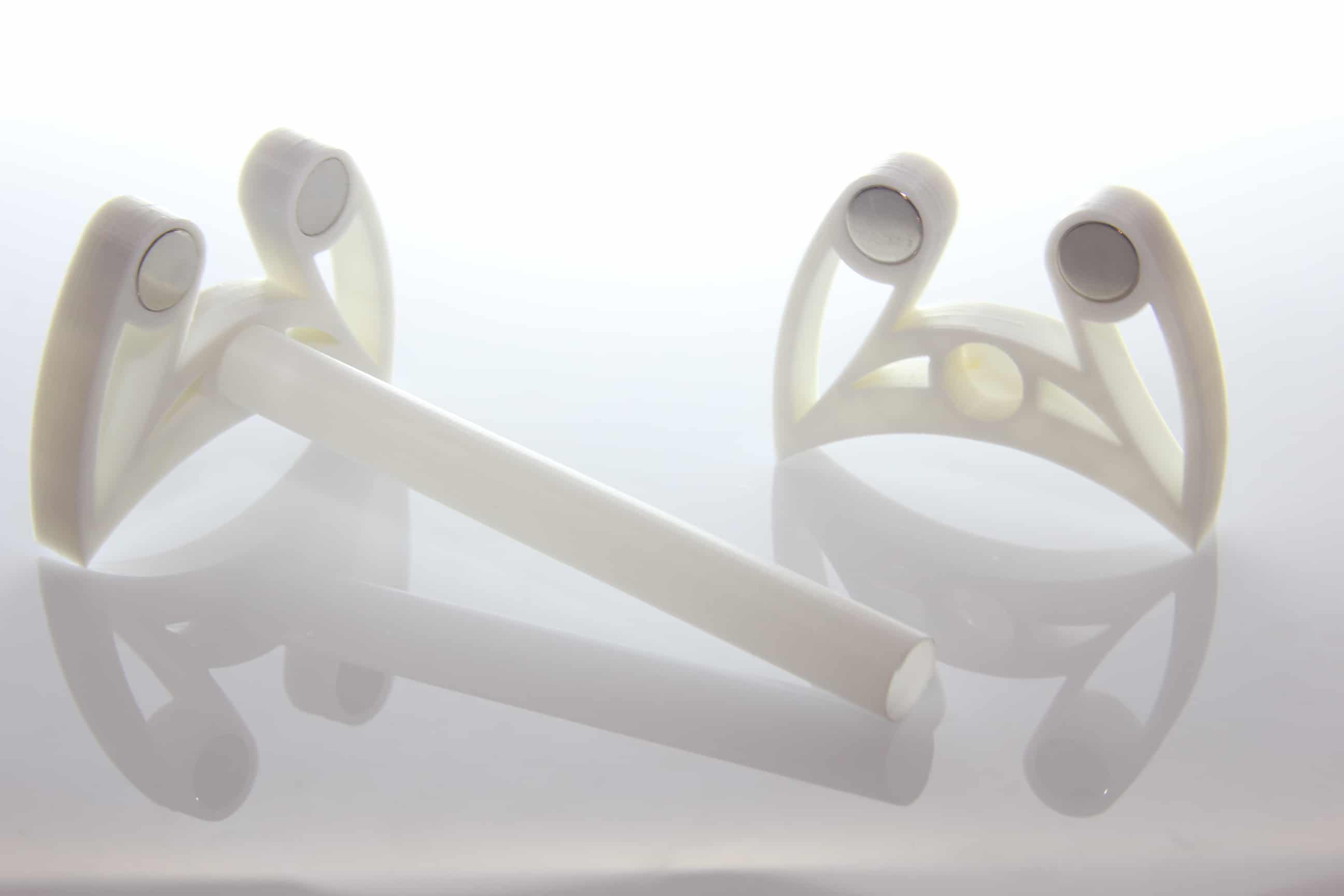
The counter-holder serves to hold the anchor with light pressure through the steel ball in the middle of the frame. For this you take the counterholder in your hand and carefully press two of the small 3mm magnets into the holes provided. The magnets must be aligned so that the backstop sticks back to back with the side panels.
The third small 3mm magnet you now push into the groove of the counter-holder. This magnet can be moved freely in it and later helps to keep the anchor at an ideal height with the help of the steel ball and to store it almost friction-free.
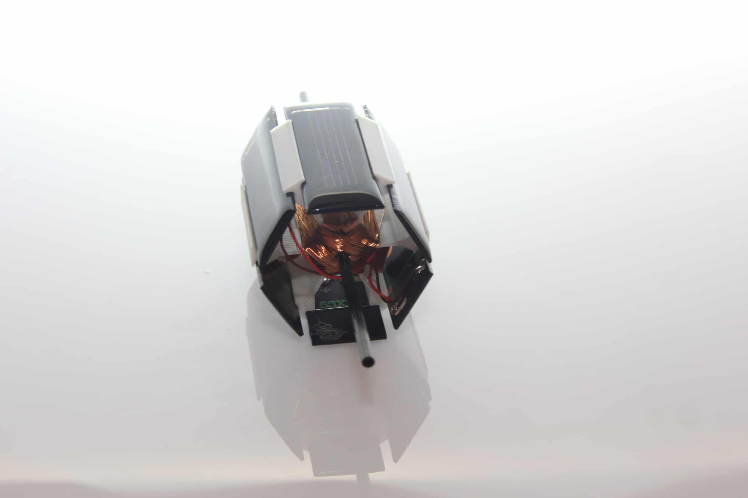
The anchor structure For this you take the 3mm carbon fiber tube and put it in the middle of the anchor. Now follows the winding of the anchor. Important: three coils are required, all of which have the same number of turns and the winding direction must always be constant. Take enough time for this and count carefully while winding!
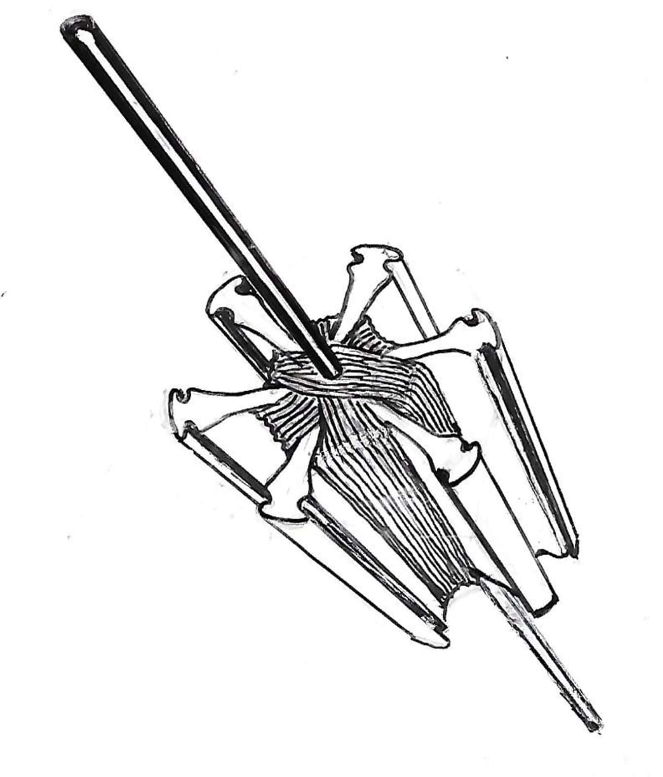
Starts with the winding of the first coil „A“. First, leave about 10cm of wire at the side and mark the wire with an marking pen, so that you can later assign the beginning of the coil. Now carefully start winding the copper wire diagonally around one of the armature slots with a light pull. To do this, you take the anchor in the left hand and wind the copper wire from top to bottom, ie clockwise around the anchor. For convenience, for example, you can wrap 20 turns to the left of the carbon fiber tube followed by 20 turns to the right of the carbon fiber tube, making counting easier. After 180 turns you let again remain about 10cm of wire, cut it off and twist both ends a little so that you find both ends of the coil „A“ more easily later. Now the winding of coil „B“ follows the same principle, followed by coil „C“. Thus, you now have an anchor package with three windings, each winding containing a wire pair of which one wire is marked.
Now follows the electrical part, the wiring and soldering of the solar cells.
Each of our three coils is connected to two solar cells, which later are mounted on the opposite sides in the armature.To do this, first carefully remove the enamelled coating of the first 3mm of the copper wire ends with a soldering iron and some solder. As a result, the enamelled copper wire loses the paint, becomes conductive and can be tinned afterwards. This procedure may take a few seconds with the soldering tip. Once the wire has received enough solder, it can then be carefully soldered to the solar cells.
Two options of interconnection (both can be easily re-soldered at any time afterwards)
1. In-series connection of the cells to the coil
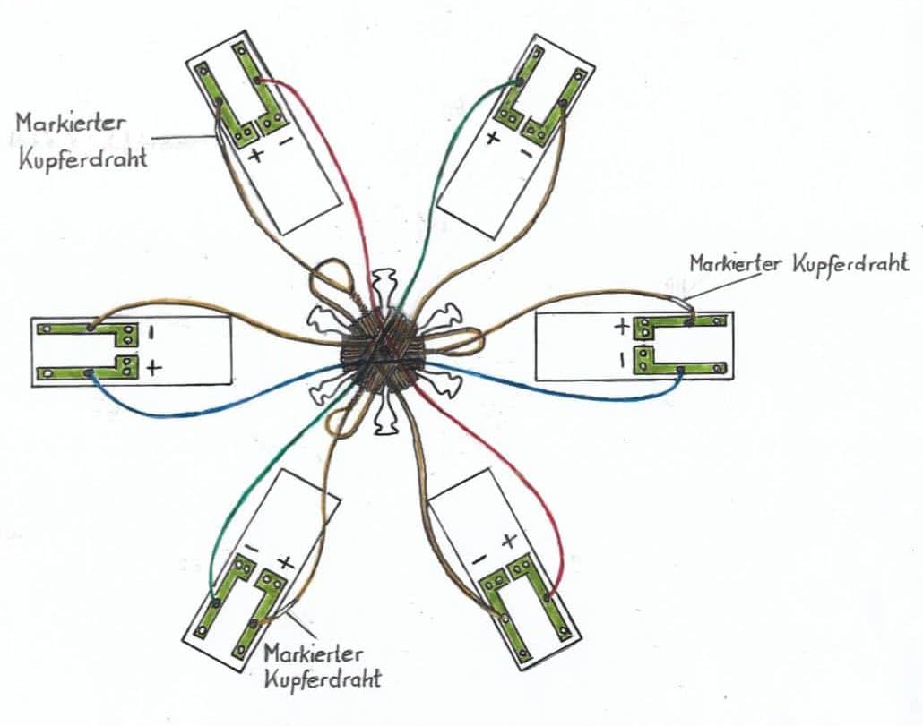
2. Parallel connection of the cells with reverse polarity of a cellWe first describe the in-series connection (as can be seen in the following sketch)
Take the marked coil input wire for the positive pole of the first solar cell. The second wire of the coil end is soldered to the second solar cell to the negative pole. Now the negative terminal of the first solar cell is connected to the positive terminal of the second solar cell with the help of one of the three enclosed cables. The circuit of the two solar cells and the wound coil is thus closed. The same procedure is repeated for coils „B“ and „C“.
Instead of the described in-series connection you can also implement a reverse polarity parallel connection.
For this you solder the marked coil input wire for the positive pole of the first solar cell. The second wire of the coil end is soldered to the minus pole on the same cell. The second cell connects you to the first cell with two wires with reversed polarity, ie +/- the first cell to – / + of the second cell.
Although this circuit requires more light, it makes the engine rotate faster.After completion of the soldering, the solar cells are inserted into the anchor. Make sure that the solder joints are not torn off. For this you push a solar cell into one of the armature slots, the second solar cell of the same coil is inserted on the opposite side of the armature. You do the same with the other cells. Now you can slide the 3D-printed side covers of the anchor on the axis and carefully snap them into the anchor.
Now follows the alignment and adjustment of the anchor. In the kit are a few thin tubes that serve as spacers and as a fixation of the anchor magnets. Two of the tubes are slightly wider and serve as loose spacers between the anchor and the magnets. The other two tubes are a bit narrower and intended to fix the magnets with some pressure at the end of the carbon fiber axis. All of these tubes can be broken to the correct length. The two axle magnets are pushed into the appropriate position using the spacer tubes. For this, finesse and a little patience is required! The magnets must be positioned in such a way that they are pushed upwards by the magnets in the side panels.
Now the counterholder is attached to the frame and aligned with the aid of the steel ball on the center of the carbon fiber tube. With this adjustment you have to move the two axle magnets until the pressure of the counter-holder and the pushback of the anchor level out and the anchor floats independently.
If you have set up everything correctly, the anchor should start to rotate with the help of a flashlight or the sun.Optimal TUNING: For the armature to rotate smoothly, it should be perfectly balanced. Winding and minimal weight differences in the solar cells may cause the armature to have minimal imbalance and to swing open as it rotates. With the help of the holes in the anchor caps, you can insert some weight, for example a part of a toothpick, and thereby optimally balance the anchor. For balancing no magnetic material may be used, so no ferromagnetic metal!
You will see, the better the armature is balanced, the less light you need to operate it endlessly!The fine tuning requires a little finesse.
In order for the armature to be running smoothly, the kit includes a mini steel ball. This is held between the carbon fiber tube and the counter-holder with the help of another mini magnet and serves as a ball bearing. On the OPEN-DIY-PROJECTS page you can also watch a matching StopMotion movie. -
AutorBeiträge
- Du musst angemeldet sein, um auf dieses Thema antworten zu können.